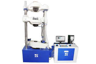
Front Open With Hydraulic Grips Computerized Universal Testing Machine

Features :
Universal Testing Machines have a wide range of applications and number of materials, metals in different form and shapes can be tested for variety of tests like Tension, Compression, Transverse, Bend, Shear, Brinell Hardness etc.Special attachments are also available for testing of Flat Belts, Chain Links, Wire Ropes etc.
Loading Frame :
The base has a hydraulic cylinder at its center and two main screws at both ends. The middle cross head is mounted on screws through main nuts. The middle cross head can be moved up or down through chain transmission and geared motor to adjust the initial tensile/compression clearance. Inside base of machine, hydraulic cylinder is sested in which piston is placed on the piston, rests an assembly of upper, lower cross head and two columns.The individually lapped cylinder piston assembly ensures smooth axial force with minimum friction.
Control Panel :
Hydraulic circuit it consists of hydraulic power pack which has a directly driven radial plunger pump which gives continuous non pulsating flow of oil pressure up to 250bar a pressure compensated needle type flow control valve is obtained with help of valves. Optionally this can be controlled form electronic system.
Loading Rate / Straining Rate Control :
This is superfine controlling system which controls loading rate / straining rate as per commands from electronic machine control system. FINE UTM Software can send loading rate / straining rate to electronic system for fully automatic testing.
Load Measurement System :
The oil pressure in the main cylinder is also transferred to an electronic pressure transducer which gives proportionate signal to electronic unit. Both the motors for hydraulic operation and cross head motion are controlled by buttons on electronic control system and they have interlocked to prevent simultaneous working of motors. The electrical panel is housed in control panel. Displacement measurement is carried out by means of a rack and pinion on rotary encoder. Encoder signal is fed to electronic system to get displacement.
Operation :
Tension test is conducted by gripping the test specimen in the upper and middle cross head. Compression, Bending, Transverse, Shear and Hardness tests are conducted between the middle and lower cross head by using appropriate fixtures. The rapid adjustment of middle crosshead facilitates easy fixing of tensile / Compression specimens of different lengths.
Hydraulic controls are through hand operated valve, ergonomically placed for ease of control. Optionally valves can be controlled form electronic control system.Adequate safeties for over load and over travel are incorporated and emergency switch is provided.
Accuracy & Calibration :
Every machine is calibrated in accordance with procedure laid down in BS-1610-1964 IS 1828-1991. 'FMI' Computerised Universal Testing Machines comply with gradeAof BS 1610-1964 and Grade 1.0 of IS 1828-1991. An accuracy of ± 1% guaranteed from 2% to 100% of capacity of the machine. In the computerised UTM, the computer is an integral part of the entire system and not just on ADD ON feature. This puts a lot of power and versatility into the hands of the operator and makes the system much more self contained than usual, as it includes many functions usually only available as additional (often expensive) optional features.
Features of FINE UTM software :
- Menu driven form system with colour graphs to compare sample test results
- Test details and reports are stored in database
- User programmable master test templates
- User can select test from master test Templates and can start similar test
- Load and Elongation is continuously displayed on screen
- Overload protection for machine by electronic control
- Tare Load and Reset Elongation facility available
- User selectable sample break detect condition
- Load rate and strain rate are also displayed while testing
- Unlimited Load rate and strain rate control steps
- With Load rate controller, user can hold the load on specimen for unlimited time
- With Load rate control, user can specify positive or negative Rate of Loading
- User selectable units for load and displacement (kg, kN,N, Ibf, mm, cm, inch etc.) Results and graphs are automatically displayed accordingly
- On line display of Load and Displacement (Stress, Extension, Strain) etc. while test is conducted
- Provision of auto zeroing of Elongation at preload set by user
- User Programmable Reports. User can select Header, Footer, Specimen information, Dimensions, Testinformation, Test results, Stastical analysis as per his need
- Generated reports can be exported to PDF file and can be e-mailed
- If electronic extensometer is used then proof stress values from 0.1% to1%can be determined
- Software will give alert to user to remove extensometer when load crosses .2% of Gauge length selected then proof load value is calculated. (With extensometer)
- Separate graph of extensometer and encoder is displayed
- Provision of calculation of Load and Elongation at yield, Peak load and Load at break, Yield stress, Ultimate stress etc
- Special software for tensile, compression, bend, TOR steel and other test software as per customer requirements

Sample Colored Multigraph for test :

A Micro controller based machine control system :
- SFull fledged sealed membrane alpha numeric keyboard for data entry
- 16 x 2 Lines LCD Graphics display with backlit for displaying Load and Elongation of crosshead with bigger font size
- Load indicated with resolution of 0.01% of machine capacity for entire range
- Elongation is measured with resolution of 0.01 mm.
- Controller for load rate and strains rate control
- Auto detection of overload and over travel and specimen break. On detection of any condition hydraulic system is automatically turned of
- Tare load and Reset Elongation facility Peak Load and Elongation at Peak, Load at break
- Elongation at break, UTS, %Elongation, %reduction in area ,Yield load etc. results for offline test
- RS232C interface for computer connectivity
- Built in centronics parallel port / Serial Port for printer interface

Technical Specification For Analogue Versions :
Specifications | Models | |||||
TFUC-100 | TFUC-200 | TFUC-400 | TFUC-600 | TFUC-1000 | TFUC-2000 | |
Measuring Cap. (kN) | 100 | 200 | 400 | 600 | 1000 | 2000 |
Measuring Range. (kN) | 0-100 | 0-200 | 0-400 | 0-600 | 0-1000 | 0-2000 |
Least Count (kN) | 0.005 | 0.01 | 0.016 | 0.024 | 0.04 | 0.08 |
Load Range in kN with accuracy of Measurement ± 1% |
2 to 100 | 4 to 200 | 8 to 400 | 12 to 600 | 20 to 1000 | 40 to 2000 |
Resolution of Piston movement (mm) | 0.01 | 0.01 | 0.01 | 0.01 | 0.01 | 0.01 |
Max. tensile clearance at fully descended piston position | 50 to 700 | 50 to 700 | 50 to 700 | 50 to 800 | 50 to 850 | 50 to 900 |
Maximum clearance for Compression test (mm) | 0 - 700 | 0-700 | 0-700 | 0-800 | 0-850 | 0-900 |
Distance between columns (mm) | 450 | 500 | 500 | 600 | 750 | 850 |
Piston Stroke (mm) | 150 | 200 | 200 | 250 | 250 | 300 |
Maximum straining speed at no load (mm/min) | 300 | 150 | 150 | 100 | 80 | 45 |
Power Supply | 3 phase 415V 50 / 60 Hz A.c. | |||||
H. P. (Total) | 1.5 | 1.5 | 2.5 | 2.5 | 4.0 | 6.5 |
Overall dimensions (Approx) (mm L x W x H) | 1950 * 800 * 1850 | 2000 * 800 * 1900 | 2100 * 800 * 2060 | 2200 * 800 * 2400 | 2350 * 800 * 2700 | 3000 * 800 * 3600 |
Weight (Approx in kg) | 1300 | 1400 | 2000 | 3000 | 4200 | 10000 |
Other Special Accessories :
- Load stabilizer for maintaining desired load
- Extensometer (Mechanical type)
- Extensometer (Electronic type)
- Printer, plotter, UPS
- Attachments for Brinell Test, Shear Test,
- 180 Bend Test Nut & Bolt Testing, Bend Re-bend etc
- Attachment for testing of wire ropes
Notes :
- Special attachment for specific test requirement can also be supplied
- Load stabilizer should be ordered along with machine itself
Standard accessories :
Specifications | Models | |||||
TFUC-100 | TFUC-200 | TFUC-400 | TFUC-600 | TFUC-1000 | TFUC-2000 | |
Tension Test JAWS For : |
||||||
Round specimen dia (mm) | 10 - 20 | 10-20 | 10-25 | 10-25 | 10-25 | 20-40 |
Round specimen dia (mm) | 20-30 | 20-30 | 25-40 | 25-40 | 25-45 | 40-60 |
Round specimen dia (mm) | - | - | - | 40-55 | 45-70 | 60-80 |
Flat specimen Thickness (mm) | 0 - 10 | 0-10 | 0-15 | 0-15 | 0-22 | 0-22 |
Flat specimen Thickness (mm) | 10 - 20 | 10-20 | 15-30 | 15-30 | 22-44 | 22-45 |
Flat specimen Thickness (mm) | - | - | - | - | 44-65 | 45-70 |
Max. width for Flat specimen (mm) | 50 | 50 | 65 | 70 | 70 | 90 |
For Compression Test : |
||||||
Pair of Compress Plates dia Ø(mm) | 120 | 120 | 120 | 120 | 160 | 220 |
For Transverse Test : |
||||||
Adjustment roller supports width (mm) | 150 | 150 | 150 | 160 | 160 | 200 |
Diameter (mm) | 30 | 30 | 30 | 50 | 50 | 70 |
With Max. adjustable clearance (mm) | 450 | 500 | 500 | 600 | 800 | 900 |
Punch Taps of Radius (mm) | 6 | 6 | 6 | 16 | 16 | 30 |
Radius (mm) | 12 | 12 | 12 | 22 | 22 | 40 |