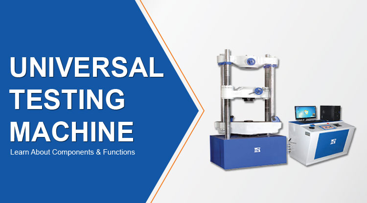
Universal Testing Machine: Learn About Components & Functions
A universal testing machine (UTM), also known as a universal tester,[1] materials testing machine or materials test frame. The term ‘universal’ usually means that it is versatile enough that it can be used in all applications. It means that our machines can be simply modified to fit the unique testing needs and requirements of your company.
Components of Universal Testing Machine
Two primary components make up a universal testing machine as follow:
- Loading Unit
- Control Unit
Loading Unit
The loading unit controls how the test specimen is set up and how much force is applied. The table and crosshead on the left unit make up the loading unit. Control unit is the right component with a load indicator layout.
The following components make up a UTM's loading unit:
Load Frame
A universal testing device's load frame can be constructed using a single support or two supports. The upper crosshead, lower crosshead, and table that the specimen is set on for the compressive strength test make up the load Frame.
Upper Crosshead and Lower Crosshead
The test specimen is clamped at one end using the top crosshead. The moveable crosshead in the load frame is the lower crosshead, and its screws can be loosened and tightened to change the crosshead's height. A tapered slit runs through the middle of each crosshead. The tensile test specimen is supposed to be held in place by a pair of racking jaws that are located in this slot.
Elongation Scale
The elongation scale that is included with the loading unit measures the relative motion of the upper and bottom tables.
Control Unit
The control unit provides the adjustments in load application and the associated test result.
The following are the primary parts of a universal testing machine's control unit:
- 1. Hydraulic Power Unit
- 2. Load Measuring Unit
- 3. Control Devices
Hydraulic Power Unit
This component consists of an oil pump that feeds steady oil into the load unit's main cylinder. The specimen is loaded more easily thanks to this flow. An electric motor and sump operate the oil pump in a hydraulic power unit.
Load Measuring Unit
The pendulum dynamometer in this device travels with the flow of non-pulsating oil in a tiny cylinder. Through a pivot lever, the pendulum is linked to the piston. Depending on the load placed on the sample, the pivot lever will flex.
The load pointer is created from this deflection and shown as the weight on the dial. A knob in the load measuring device allows the user to change the load application range. The measurement unit's precision determines the machine's accuracy rate.
Control Devices
The controls could be hydraulic or electronic. Switches are used by electric control devices to move the crossheads and turn the unit on and off. Two valves—the right control valve and the left control valve or release valve—make up a hydraulic control device. The specimen is subjected to load using a proper control valve.
Functions of UTM
UTM is mostly used to assess the mechanical characteristics of materials. UTM regularly conducts the following tests:
- 1. Tensile Test
- 2. Adhesion Tests
- 3. Bending Test
- 4. Hysteresis Test
- 5. Compression Test
- 6. Pull-Out Tests
Materials that can be tested by UTM:
- Concrete
- Steel
- Winches
- Steel Ropes
- Cables
- Springs
- Steel Wires
- Slings
- Links
- Rope
- Chains
